Circuit Diagram For Photodiode Arduino Photodiode Circuit Wiring. The wiring diagram for this example project is shown in the previous section, scroll up and check it out. Below is an image of how the whole setup looks like at the end, ready for the test. Arduino Photodiode Light Sensor Circuit #1. Arduino Photodiode Light Sensor OpAmp Circuit #2. Code Example
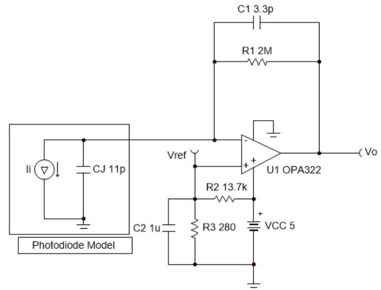
A simple photodiode circuit with an amplifier . Note that a photodiode can also be used to receive digital data encoded in modulated optical pulses. This is typically done by applying pulse width modulation or amplitude modulation to the light source. In the case of pulse width modulation, you will need to account for the frequency limitations
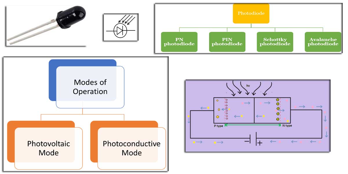
Photodiodes and Photoconductors Tutorials Circuit Diagram
I'm trying to design a circuit to measure the ambient visible light (380nm to 750nm). Accuracy isn't too important. I've been looking at photodiodes, but I'm not sure how to connect them up. I need the following requirements from my circuit: low power; low accuracy; low cost photodiode (e.g. this on digikey) AD convert signal for uC

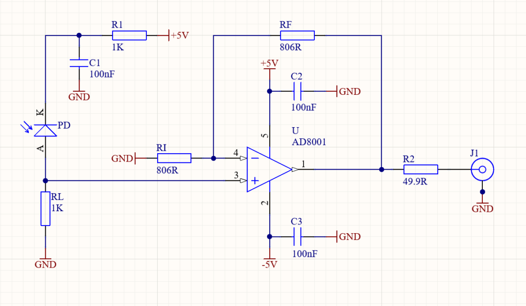
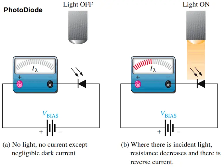
The following two applications circuits show how a foolproof implementation can be done using photodiodes through 30 kHz carrier modulation frequency. These are selective preamplifier based photodiode alarm circuits, and will respond to a specific band of frequency, ensuring a foolproof operation of the system. In the above circuit you can notice that voltage divider setup using Photodiode and resistor R1. The voltage developed between these two components is fed to inverting input of Opamp. Meanwhile another voltage divider using resistor R2 and R3 is used to create a reference voltage, adjust R3 to fix the reference voltage. Photodiodes need to be treated in a special way ! 1) use the diode in zero-bias or reverse mode (not in forward mode) 2) when dark, no current flows through the photodiode. 3) a circuit is needed to "catch" the photocurrent and amplify it. Here's an example of such a circuit: This circuit is called a transimpedance amplifier.
Photodiode : Working and how to use in circuits Circuit Diagram
Two different ways to use a photodiode. In the photovoltaic circuit, you connect the photodiode in forward-biased mode. The anode of the photodiode is connected to the non-inverting terminal and the cathode to the inverting terminal of the op-amp. When light falls on the photodiode, it generates a small voltage and current. This circuit is designed to detect light levels using a photodiode and control an LED based on the detected light. The Arduino UNO reads the voltage across the photodiode connected to its analog pin A0 and turns on the LED connected to digital pin D3 through a 220 Ohm resistor if the light level falls below a predefined threshold.