Oscilloscope Triggers A quick what and how Circuit Diagram How do you read an oscilloscope value? To read an oscilloscope value, you need to understand the three main types of measurements: amplitude, time, and voltage. These are the three key characteristics that will be represented on any oscilloscope reading. When you take a measurement with an oscilloscope, you will see a trace on the screen that Learn what an oscilloscope measures. An oscilloscope measures the voltage of an electrical current. Unlike a multimeter (which only measures the RMS voltage), an oscilloscope takes multiple voltage measurements and plots them on a graph in the form of a wave pattern. This allows you to see exactly what the voltage is doing overtime.
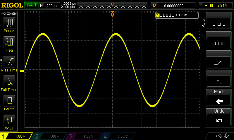
An oscilloscope, really, does only one thing: it captures a representation of a live signal from a test circuit and displays it on a screen. Based on the information that the oscilloscope captures about the signal, modern digital oscilloscopes ofter two other important functions: to measurement of various parameters of the signal and decode This video shows how to read an oscilloscope and shows how to take those reading and convert them to frequency and required amplitudes. This equipment is in
Oscilloscope How To : 10 Steps (with Pictures) Circuit Diagram
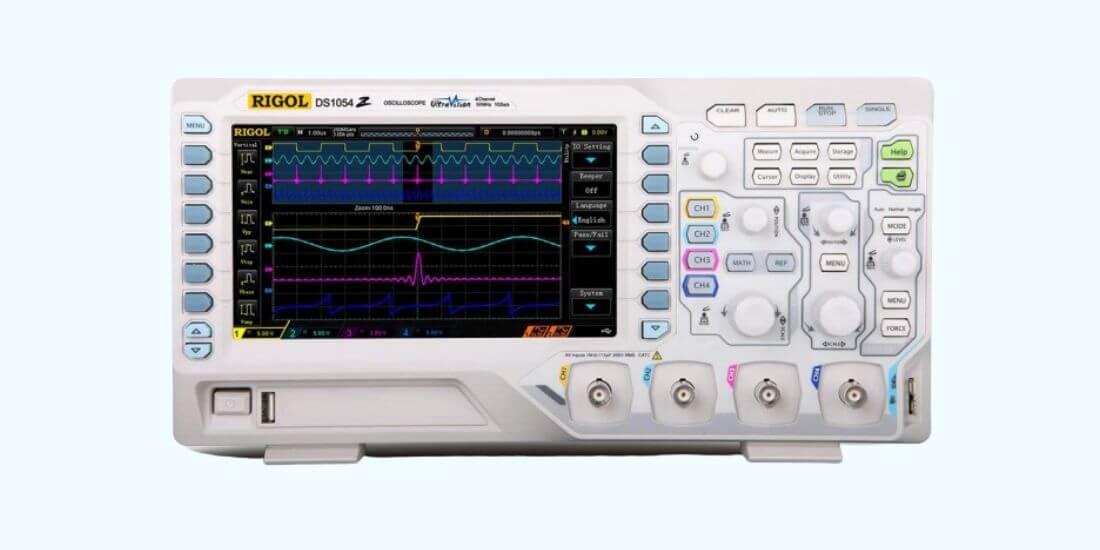
If your oscilloscope has multiple channels, you can look at multiple inputs at the same time. This is especially useful for looking at changes in a signal as it moves through your circuit. I set up a pulse-like waveform and put it through a simple voltage follower/buffer circuit to measure the slew rate of an op amp .
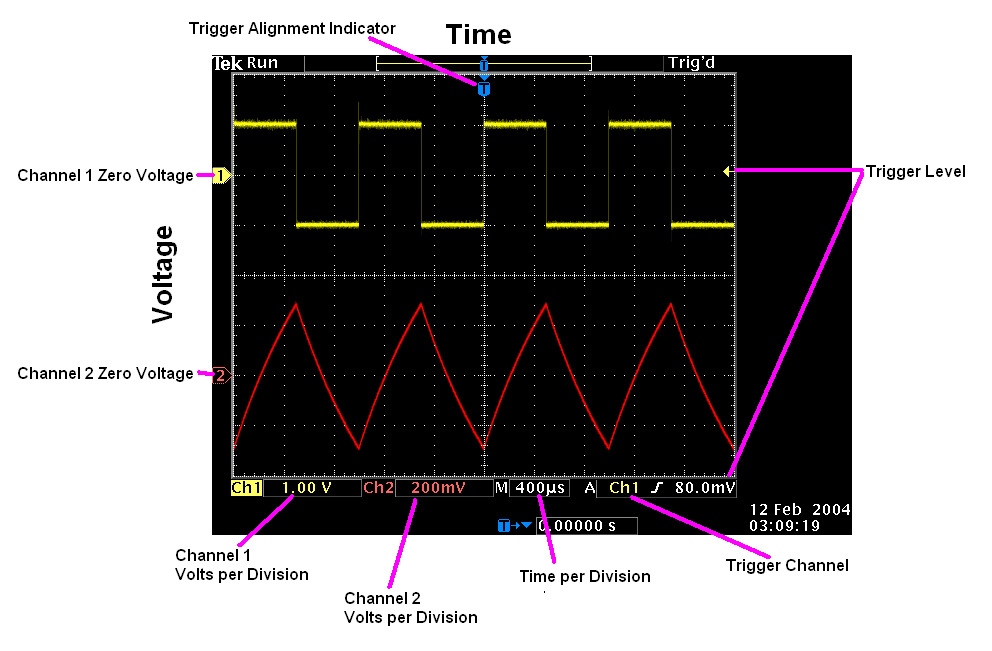
What is an oscilloscope? An oscilloscope (informally scope, oscope, or O-scope) is a diagnostic instrument that draws a graph of an electrical signal.. View the complete lineup of Tektronix oscilloscopes » Oscope Basics. Oscilloscopes are versatile electronic instruments that are commonly used by engineers to perform waveform and signal analysis in electronic circuits. Learn how to interpret oscilloscope waveform readouts and extract key signal details. Find out what is measured on the x- and y-axis, how to measure frequency, voltage, and phase, and what are the common waveforms displayed on an oscilloscope screen. Understanding how to read oscilloscope waveforms is essential for success in electronic engineering and troubleshooting. By mastering the basic controls, waveform interpretation techniques, and advanced features, you can harness the power of the oscilloscope to analyze signals effectively, debug circuits, and optimize performance.
4 Ways to Use the Oscilloscope Circuit Diagram
Learn the basics, terminology, and features of oscilloscopes, tools that graph electrical signals over time. This tutorial covers how to use an oscilloscope to measure frequency, amplitude, noise, and more.
